Sunspot Home

more backup notes for a bad memory - - -
(Not finished but working)

Using an Arduino UNO with colour LCD display connected to Raspberry Pi by ESP8266 WIFI

Objective
Display home network IOT information on LCD connected to a Raspberry Pi by WIFI

3.2 Inch 320 X 240 TFT LCD Display Module for £3.09
You can now get UNO clones for less than £2
Add an ESP8266-01 and have a display that shows LAN data (temperatures etc collected by a Raspberry Pi) wherever there is power


Raspberry Pi Blassic control program

Three thermistors on an Arduino Nano in the greenhouse connect to the Pi by i2c
A string of bytes is assembled in uno_data$ and saved to ramdisk in file uno_data.txt
A high and a low byte for each of three thermisters.

nc -u -w 3 192.168.0.180 9999 < /var/www/ramdisk/uno_data.txt in the Pi grabs uno_data.txt and sends the data to ESP8266

I find that a byte 0 (NULL character) in the string sent to the ESP causes the transmission to stop
So I add 1 to the high byte at the Pi end and subtract it in the UNO (the maximum integer I need is 1024)

#!/usr/sbin/blassic

' /home/graham/housekeeping/stringsforUNOESP2.bas

' i2c address 4 to get data
thermister_C_driver$ = "/home/graham/UTFT_display/Pi-Ard_send_3_bytes_get_6_from_Nano 4 3 255 255"
'PRINT thermister_C_driver$
SHELL thermister_C_driver$

PAUSE 4000

OPEN "/var/www/ramdisk/from_arduino0.dat" FOR INPUT AS #1:INPUT #1,arduino_byte_0$:CLOSE #1
OPEN "/var/www/ramdisk/from_arduino1.dat" FOR INPUT AS #1:INPUT #1,arduino_byte_1$:CLOSE #1
OPEN "/var/www/ramdisk/from_arduino2.dat" FOR INPUT AS #1:INPUT #1,arduino_byte_2$:CLOSE #1
OPEN "/var/www/ramdisk/from_arduino3.dat" FOR INPUT AS #1:INPUT #1,arduino_byte_3$:CLOSE #1
OPEN "/var/www/ramdisk/from_arduino4.dat" FOR INPUT AS #1:INPUT #1,arduino_byte_4$:CLOSE #1
OPEN "/var/www/ramdisk/from_arduino5.dat" FOR INPUT AS #1:INPUT #1,arduino_byte_5$:CLOSE #1

PRINT "arduino_byte_0$ for screen = ",arduino_byte_0$
PRINT "arduino_byte_1$ for screen = ",arduino_byte_1$
PRINT "arduino_byte_2$ for screen = ",arduino_byte_2$
PRINT "arduino_byte_3$ for screen = ",arduino_byte_3$
PRINT "arduino_byte_4$ for screen = ",arduino_byte_4$
PRINT "arduino_byte_5$ for screen = ",arduino_byte_5$

in1 = 2
in2 = VAL(arduino_byte_0$) + 1
in3 = VAL(arduino_byte_1$)
in4 = VAL(arduino_byte_2$) + 1
in5 = VAL(arduino_byte_3$)
in6 = VAL(arduino_byte_4$) + 1
in7 = VAL(arduino_byte_5$)

PRINT in1
PRINT in2
PRINT in3
PRINT in4
PRINT in5
PRINT in6
PRINT in7

uno_data$ = chr$(in1) + chr$(in3) + chr$(in2) + chr$(in5) + chr$(in4) + chr$(in7) + chr$(in6)
PRINT uno_data$

OPEN "/var/www/ramdisk/uno_data.txt" FOR OUTPUT AS #1:PRINT #1,uno_data$:CLOSE #1

SHELL "nc -u -w 3 192.168.0.180 9999 < /var/www/ramdisk/uno_data.txt"

SYSTEM


ESP8266 program to receive UDP data from Pi and send it to the UNO via serial

Serial.println(packetBuffer) sends the string to the UNO
and to a CoolTerm serial monitor in the iMac for testing via serial to USB
port.write sends data to the Pi via WIFI

#include <ESP8266WiFi.h>
#include <WiFiUdp.h>

WiFiUDP port;

char packetBuffer[255];
unsigned int localPort = 9999;

void setup() {
Serial.begin(115200);
WiFi.begin("Link", "uu8diode");

IPAddress ip(192, 168, 0, 180);
IPAddress gateway(192, 168, 0, 230);
IPAddress subnet(255, 255, 255, 0);
WiFi.config(ip, gateway, subnet);

port.begin(localPort);

}
void loop() {
int packetSize = port.parsePacket();
// Serial.println(packetSize);
if (packetSize) {
int len = port.read(packetBuffer, 255);
if (len > 0) packetBuffer[len-1] = 0;
Serial.println(packetBuffer);

//Note - Serial.write(packetBuffer); also has trouble understanding null string
// what is the correct way to send a zero value byte?

port.beginPacket(port.remoteIP(),port.remotePort());

port.write("Your UDP packet was received OK\r\n");
port.write("180");
port.write("\r\n");
port.endPacket();
}
delay(500);
}


The UNO program that receives the serial data string and displays the data on the LCD


//±±±±±±±±±±±±±±±±±±±±±±±±±±±±±±±±±±±±±±±±±±±±±±±±±±±±±±±±±±±±±±±±±±±±±
#include <Adafruit_GFX.h> // Core graphics library
#include <Adafruit_TFTLCD.h> // Hardware-specific library
// The control pins for the LCD can be assigned to any digital or
// analog pins...but we'll use the analog pins as this allows us to
// double up the pins with the touch screen (see the TFT paint example).
#define LCD_CS A3 // Chip Select goes to Analog 3
#define LCD_CD A2 // Command/Data goes to Analog 2
#define LCD_WR A1 // LCD Write goes to Analog 1
#define LCD_RD A0 // LCD Read goes to Analog 0

#define LCD_RESET 10 // NB! to avoid i2c pin A4 - rewire the board A4 to D10

// Assign human-readable names to some common 16-bit color values:
#define BLACK 0x0000
#define BLUE 0x001F
#define RED 0xF800
#define GREEN 0x07E0
#define CYAN 0x07FF
#define MAGENTA 0xF81F
#define YELLOW 0xFFE0
#define WHITE 0xFFFF

Adafruit_TFTLCD tft(LCD_CS, LCD_CD, LCD_WR, LCD_RD, LCD_RESET);
// Adafruit_TFTLCD tft;
//±±±±±±±±±±±±±±±±±±±±±±±±±±±±±±±±±±±±±±±±±±±±±±±±±±±±±±±±±±±±±±±±±±±±±

//int command = 0;
byte data[30];
word combined1 = 0; //- - word or double needed here - int fails (why??)
word combined2 = 0;
word combined3 = 0;
int x;
int s = 0;
int c = 0;
int z;
int xx; // x coordinate
int yy; // y coordinate
int cc; // my colour code
float temp0x10;
float temperature0;
float temp1x10;
float temperature1;
float temp2x10;
float temperature2;
int newdata = 1;
int rewipe = 1;

//=====================================================================================================setup START
void setup() {
Serial.begin(115200);
Serial.println("STARTING");

//±±±±±±±±±±±±±±±±±±±±±±±±±±±±±±±±±±±±±±±±±±±±±±±±±±±±±±±±±±±±±±±±±±±±±
Serial.println(F("TFT LCD FONT test"));
#ifdef USE_ADAFRUIT_SHIELD_PINOUT
Serial.println(F("Using Adafruit 2.8\" TFT Arduino Shield Pinout"));
#else
Serial.println(F("Using Adafruit 2.8\" TFT Breakout Board Pinout"));
#endif
Serial.print("TFT size is "); Serial.print(tft.width()); Serial.print("x"); Serial.println(tft.height());
tft.reset();
uint16_t identifier = tft.readID();
if(identifier == 0x9325) {
Serial.println(F("Found ILI9325 LCD driver"));
}
tft.begin(identifier);
//±±±±±±±±±±±±±±±±±±±±±±±±±±±±±±±±±±±±±±±±±±±±±±±±±±±±±±±±±±±±±±±±±±±±±

pinMode(13, OUTPUT);
}
//========================================================================================LOOP START
void loop () {

Flash_LED_13(); //show we are alive
rewipe = rewipe + 1;
//get data from serial
x=0;
while(Serial.available()) {
data[x] = Serial.read();
if (x == 2) {data[2] = data[2] - 1;} // sending 0 (null) stops the data transfer so add 1 then remove it here for the high bytes
if (x == 4) {data[4] = data[4] - 1;}
if (x == 6) {data[6] = data[6] - 1;}
Serial.print( " data = ");
Serial.println(data[x]);
x++;
newdata = 1;
}

if (newdata == 1){ DriveLCD(); }
if (rewipe == 3){ DriveLCD(); }
delay (3000);
}
//========================================================================================LOOP END

unsigned long DriveLCD() {

combined1 = word(data[2],data[1]); //high-data[2] and low-data[1] bytes combine here
temp0x10 = combined1;
temperature0 = temp0x10/10;
temperature0 = temperature0 - (20 - temperature0) * 1.5/20;

combined2 = word(data[4],data[3]);
temp1x10 = combined2;
temperature1 = temp1x10/10;
temperature1 = temperature1 - (20 - temperature1) * 1.6/20;

combined3 = word(data[6],data[5]);
temp2x10 = combined3;
temperature2 = temp2x10/10;
temperature2 = temperature2 - (20 - temperature2) * 1.5/20;

tft.fillScreen(WHITE);

tft.setTextSize(3);

tft.setCursor(2, 2); tft.setTextColor(BLACK);
tft.print("G1South "); tft.println(temperature0, 1);

tft.setCursor(2, 32); tft.setTextColor(BLACK);
tft.print("G1West "); tft.println(temperature2 , 1);

tft.setCursor(2, 62); tft.setTextColor(BLACK);
tft.print("outside "); tft.println(temperature1, 1);

tft.setCursor(2, 122); tft.setTextColor(BLUE);
tft.print(data[0], 1); tft.print(" "); tft.print(data[1] , 1); tft.print(" "); tft.println(data[2] , 1);
tft.print(data[3] , 1); tft.print(" "); tft.print(data[4] , 1); tft.print(" "); tft.println(data[5] , 1);
tft.print(data[6] , 1); tft.print(" "); tft.print(data[7] , 1); tft.print(" "); tft.println(data[8] , 1);
tft.print(data[9] , 1); tft.print(" "); tft.print(data[10] , 1); tft.print(" "); tft.println(data[11] , 1);

tft.setCursor(2, 250); tft.setTextColor(RED);
tft.println(" ESP8266 display");

newdata = 0; // only repaint the display if new data arrives
rewipe = 0; // reset the counter that allows screen clean-up every few loops
}

// >>>>>>>>>>>>>>>>>>>>>>>>>>>>>>>>>>>>>>>>>>>>>>>>>>>>>>>>>>>>>> FUNCTION Flash_LED_13
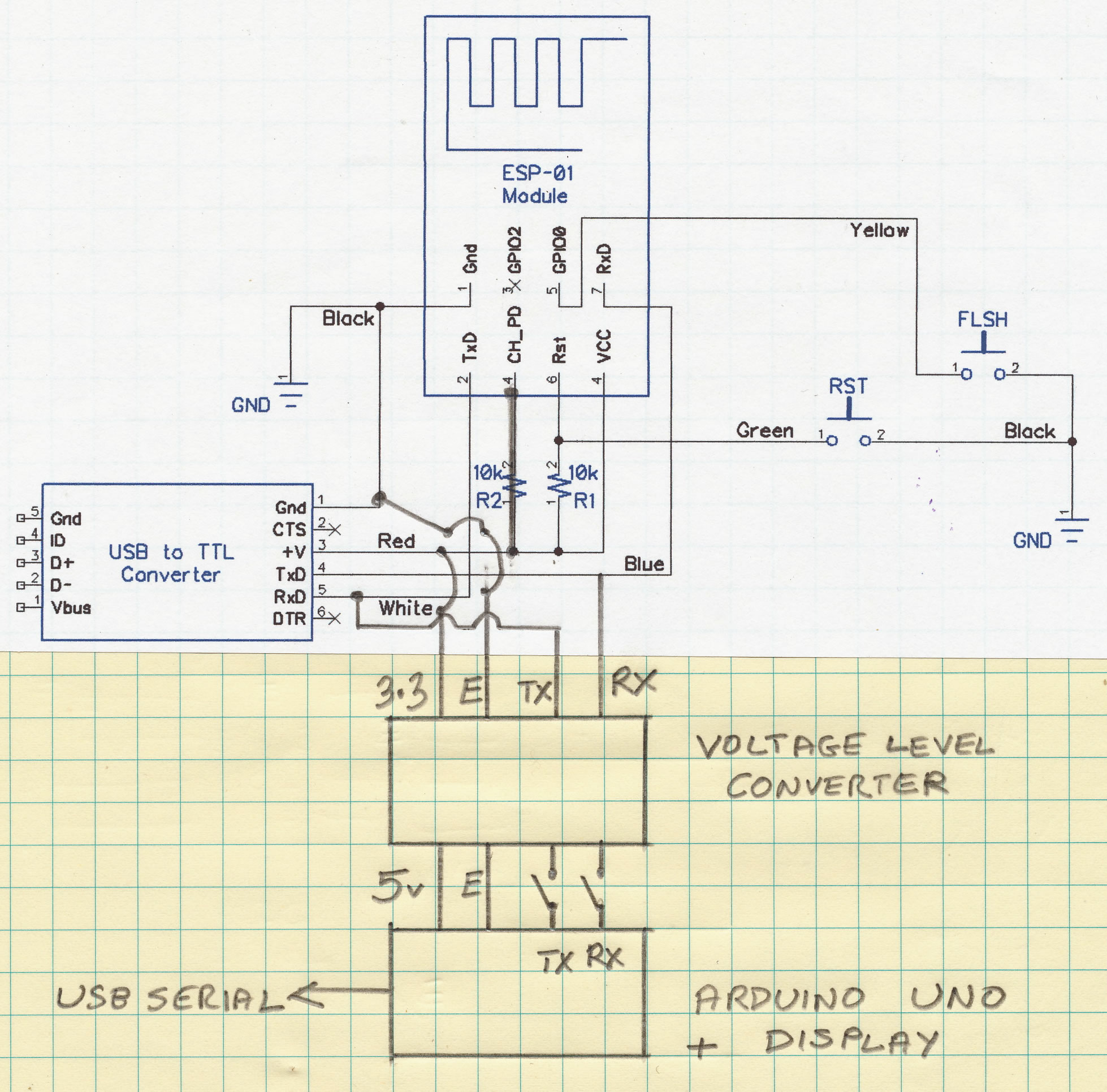
void Flash_LED_13(){
digitalWrite(13, HIGH); // set the LED on
delay(300);
digitalWrite(13, LOW); // set the LED off
delay(300);
}


Test circuit

The ESP uses 3.3 volts and the UNO uses 5 volts.
To reprogram the UNO it is necessary to disconnect the serial wires from the voltage level converter


Please email me if you want to swap notes

SUNSPOT HOME