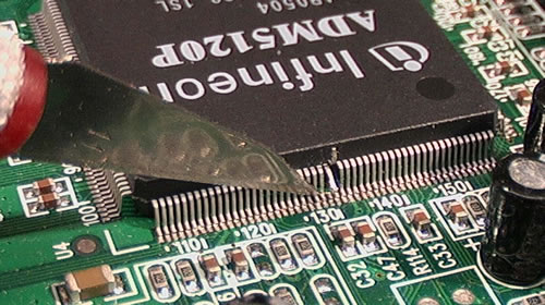
You can connect to the
second AMD5120 serial port !

UDI0
pin 127
UART 0 RX
existing
UDO0
pin 129
UART 0 TX
existing
UDI1
pin 130
UART 1 RX
blue wire - left cut pin
UDO1
pin 131
UART 1 TX
green wire - right cut pin

The craft knife or scalpel is very sharp and ends in a point.
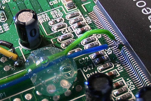
Press down hard at the bottom of the pin where it bends.
Bend the knife back and forth till you feel the pin cut through.
Use the knife point to bend the pins up so that you can solder to them

(I use a desk magnifier plus a second hand held magnifying glass)

A blob of hot glue from a glue gun holds the wires

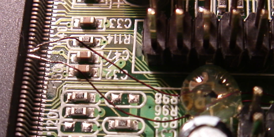
Beware of wire that is too stiff - one of 20 cpu wires I have cut failed after some months due to too much strain.
I now use enameled coil winding wire with no tension and I also take care to NOT bend the pins where they enter the plastic moulding but at the "knee"
- see below


This is a view of the layout of my general purpose
MAX3232 RS232 to logic level converter
VIEWED FROM BELOW
for NSLU2/Sweex/Edimax use 3.3V!!!!!!
It runs on 5V or 3.3V - the MAX232 (same pinout) is 5V only
- built on 0.1" matrix board.
- two of the capacitors fit within the DIL chip socket.

For the second converter within the chip -
logic level - to router pin 12 / from router pin 11
RS232 - plug pin 2 to chip pin14 / plug pin 3 to chip pin 13