Adding a digital picture frame external display to a nslu2 (Slug)
(brute force method!) some more notes for when I forget what I did.
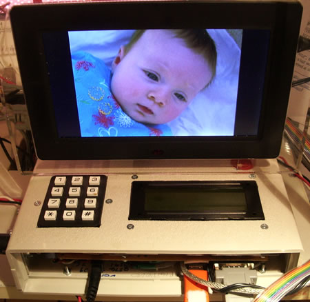
Objective Under the control of a web page viewed on a remote PC upload a picture to a Slug
and have the Slug automatically display it on an attached digital picture frame
Method
I had hoped to use the USB "gadget mode" to make the Slug look like a USB memory stick
and then plug this "stick" into the USB port of my 7" digital photo frame from eBuyer
I failed to achieve that so I built a circuit that uses transistor switches to control the physical buttons on the display under the control of a bash script triggered by the remote browser's web page.
The script controls a relay that "unplugs" a USB memory stick from the display and "plugs" it into the Slug.
The memory stick auto-connects under Debian and a script controlled from the remote browser mounts the stick and loads the picture into an archive on the hard disk and also onto the stick.
The relay then plugs the stick into the display, turns the display power on, then "presses" a button that starts the slide show.
The process takes about 20 seconds - fast enough for the purpose.
Memory sticks have limited life but do employ a process to even out the wear across all the memory cells.
A cheap 1 or 2 GByte stick should last for a long time under the anticipated load.
Circuit elements
The top of the diagram below shows the display circuit board button connections.
Reed relays are used to switch the display main board power supply and pulse the on/off toggle button.
I find that the display comes on when it receives power and the toggle on/off button is not needed at present.
A 200mSec pulse on the RETURN button tells the display to show the pictures as a slide show.
Transistors can switch the ENTER and RETURN buttons to earth.
Transistors can switch the LEFT and RIGHT buttons to the board 3.3V on pin 3 - a large value (24 K Ohm) base resistor was needed to get these to respond - odd - the 5V on the gate must have confused the display.
The I2C chip BCF8574AP 8 wire port expander pins only pull hard to earth (open collectors). PNP transistors invert the voltage to feed the reed relay NPN driver transistors.
The LEDs are on for low outputs on the port expander.
The 8574 ports are :-
0-screen main power
1-USB relay
2-on/off toggle button
4-LEFT
5-RIGHT
6-RETURN
7-free
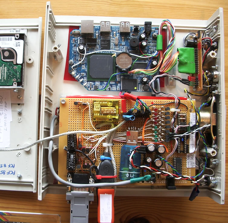
Slug with expansion board
(rs232____I2C with long line driver____USB sound___USB hard disk)
The yellow relay is used to switch the USB lines for the red memory stick that transfers pictures from the Slug to the display.
This is unscreened but works well!
A USB extender lead provided the needed USB socket and plug.
The USB sound dongle drives an on board amplifier for the loud speaker.
It speaks when a new picture has been received.
The screen USB memory stick, sound dongle and 2.5" boot disk drive are connected to the three spare USB ports on the Slug board.
A separate 5V power supply is connected to the screen via a reed relay.
Code Backup of the controlling web page and bash scripts are here
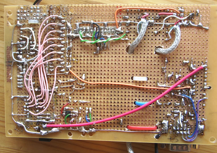
The back of the board.
The pink wires feed I2C ports to the test LEDs, push button controls, USB relay etc
The USB cable connects to the relay unscreened but it works well
!!
Only the D+ and D- data wires are switched.
A 9 pin D-Type cable (as for rs232) connects to the display.
A ribbon cable to the plug is about 12" long.
100 NF capacitors between earth and 5 Volts are at each chip.