Some pictures of the Sweex modifications
|
|
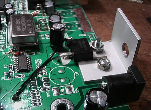
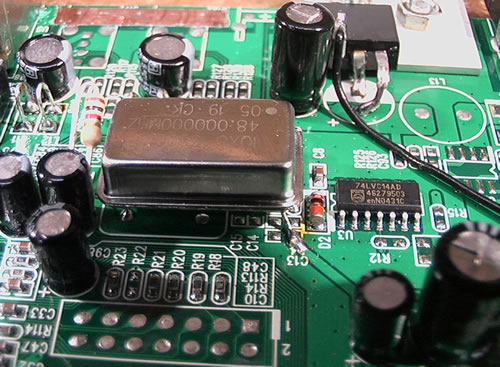
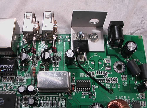
| (1) 5 volt power supply - black wire is +12V (!) | (2) The 48MHz oscillator picks up 3.3 volts near C13/D2 |
|
|
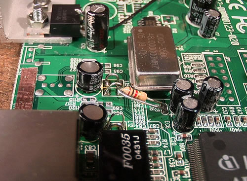
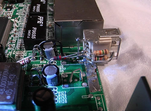
| (3) The 1 K ohm resistor for the xtal osc. Copper exposed left for USB sockets | (4) USB 15K resistors to ground, 22ohm to CPU lines |
|
|
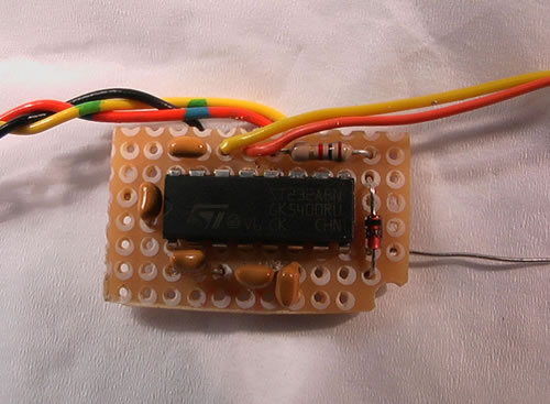
| (5) All mods prior to adding MAX232 and stereo socket to heat-sink | (6) MAX232 - 0.1mfd caps - output to Sweex via 1K to 3.3v clipping zener |
|
|
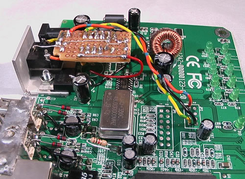
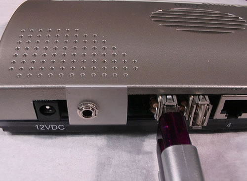
| (7) MAX232 board mounted - red wire is 5 volts - tincan strap on top of USB sockets | (8) Rear view. Stereo (RS232) socket mounted on heatsink |
NOTES -
All inspired by and thanks to the Feb 2006 Elektor project by J Domburg
(1) that
black wire should have been red and is actually +12 volts from the wall power
supply.
It will work with no heat sink but gets very hot - I would extend the heat sink
further along the back of the outside of the box next time,
especially if you power USB devices off it - see note 8
(2) The two left pins of the oscillator fit
the circuit board pads, the one on the right that you can't see is clipped off
If you obtain a miniature oscillator that fits the existing
board pads then you must connect a short across L4 to give it power
(thanks
to Phill)
(3) I
used the 1K resistor - I think some people just short it out.
(4) The side of the USB socket you see normally
goes flat to the board.
The top pin of the USB socket gets +5 Volts. The bottom one is earth
The 22 ohm resistor next to the +5 pin goes to the pad furthest from the Ethernet
sockets
The right hand end of the two 15K resistors go to earth
The two electrolytics near the USB sockets are 10 mf - not sure they are needed
since they are in
parallel with the 100 mf near the 7805 5 volt supply (note the inverted U shaped
bridges that take the place of the inductors)
(5) the 22 ohm resistors go down to a pair
of pads both connected to the USB CPU lines.
This pair are central to four pads in line. Their are four sets of four such
pads.
You can just see the four furthest away from the ethernet sockets. The label
C96 is at one end of the line.
The 22 ohm resistor can be soldered to BOTH of the inner pair of pads.
(8) More of the L shaped heat sink extrusion
could have been external - it gets fairly warm.
But I think they have thermal cut-outs! Remember that the wall power unit gives
only 500 mA
BUILD AT YOUR OWN RISK!